
NewsDetails
Drive Shaft Dynamic Balancing Standards
author:Hongye time:2026-01-26 17:27:10 Click:72
Dynamic balancing is a critical quality control process for automotive drive shafts, ensuring smooth operation by minimizing centrifugal forces generated by mass unevenness during rotation. Even minor imbalances can produce significant vibration, noise, and premature wear at high rotational speeds. The industry adheres to established standards to quantify and control this phenomenon.
The Physics of Imbalance:
An unbalanced drive shaft has its principal axis of inertia misaligned from its rotational axis. When rotated, this creates a centrifugal force proportional to the mass of the imbalance, the distance of that mass from the center of rotation, and the square of the angular velocity (F = mω²r). This rotating force excites the shaft's bending modes, transmitting vibration through the vehicle structure.
Balance Quality Grades:
The international standard ISO 1940-1 (Mechanical vibration — Balance quality requirements for rotors) provides the foundation for drive shaft balancing. Rotors are classified into balance quality grades based on their service conditions.
For automotive drive shafts, the relevant grades are typically:
G40: General purpose car, truck, and agricultural drive shafts.
G16: Passenger cars, light trucks, and high-speed drive shafts.
These grades define the maximum permissible residual specific unbalance (e<sub>perm</sub>) in millimeters per second (mm/s). The actual permissible residual imbalance (U<sub>perm</sub>) in gram-millimeters (g·mm) is calculated by multiplying the specific unbalance by the rotor mass (m): U<sub>perm</sub> = (e<sub>perm</sub> × m) .
Balancing Process:
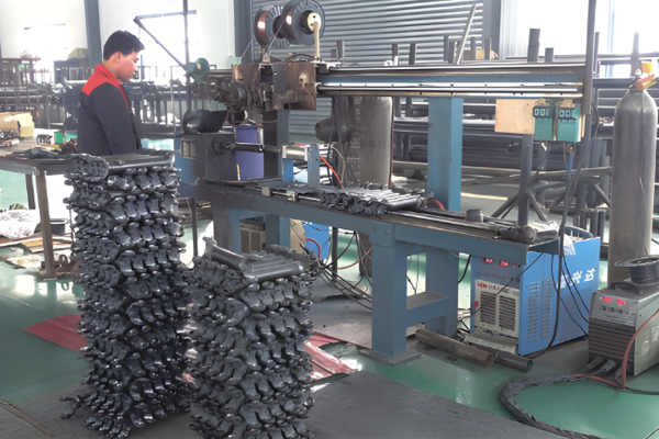
Initial Measurement: The assembled drive shaft is mounted on a balancing machine and spun at a specified test speed (typically 500–2000 RPM). Sensors measure vibration forces at the bearing supports.
Correction Calculation: The machine's instrumentation analyzes the phase and magnitude of the vibration signals, calculating the precise amount and angular location of imbalance in two correction planes (usually at each end of the shaft).
Mass Addition/Removal: Correction is achieved by welding balancing plates or weights to the shaft tube at the calculated positions, or by drilling out material from balancing pads on yokes or flanges.
Tolerance Specifications:
Typical production tolerances for passenger car drive shafts call for residual imbalance values ranging from 5 to 30 g·mm at each end, depending on shaft mass, maximum operating speed, and vehicle sensitivity. For example, a high-speed luxury sedan shaft may require less than 5 g·mm residual imbalance, while a heavy truck shaft might accept up to 50 g·mm.
Factors Influencing Standards:
The target residual imbalance is determined by:
Maximum Operating Speed: Higher speeds require tighter tolerances due to the squared relationship with centrifugal force.
Shaft Mass: Heavier shafts can tolerate higher absolute imbalance (g·mm) for the same vibration level.
Mounting Proximity: Shorter shafts with closely spaced bearings are more sensitive to imbalance.
Vehicle Application: Luxury vehicles demand stricter tolerances than commercial vehicles.
Verification and Quality Control:
After correction, the shaft is re-spun to verify residual imbalance falls within specification. Production lines typically use statistical process control to monitor balancer performance and ensure consistent quality. Some applications also specify balancing with attached components like center bearings or flex couplings to account for assembly tolerances.
Adherence to these dynamic balancing standards ensures that drive shafts operate smoothly throughout their service life, contributing to vehicle refinement, bearing durability, and overall driveline reliability.
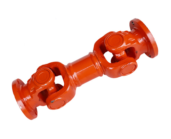
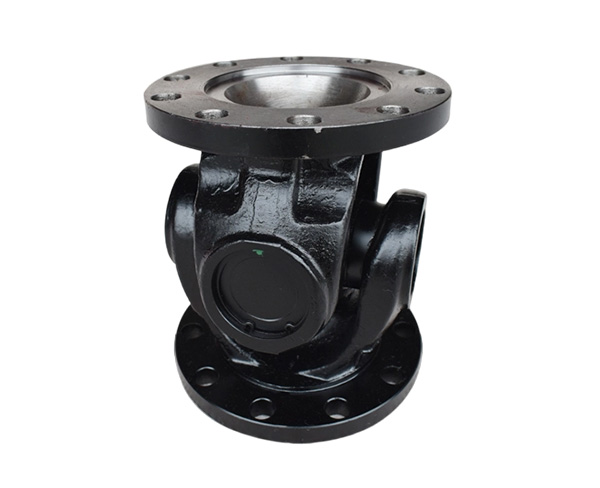
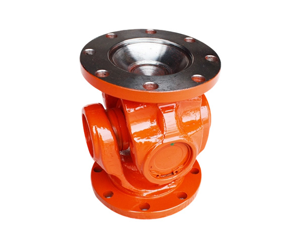
 Recommended Products
 Contact us
—— Contact:Manager
—— Tel:+86 15127708111
—— Email:jingzhou999@qq.com
—— Url:https://www.hongyeautopart.com
—— Address:Migezhuang Town, Hejian City, Cangzhou City, Hebei Province, China